Generation 2 Vanquish rear light.
This article has been written to give some idea of the problems with the modern cars. It's going to take considerable effort to ensure that these cars are still on the road in 20 years time.
The Aston Martin Vanquish (Gen 2), and all the latest Aston Martins, use LED’s for the rear lights, indicators etc. The unit detailed here was removed from a 2012 Aston Martin Gen 2 Vanquish because it’s LED’s flickered. This is a USA spec left hand unit, and the factory was out of stock of replacements. Some distributors have indicated that AML have no intention of restocking. This car was awaiting a replacement when this article was being written.
The replacement cost is £3,500 each!
It was decided to open up the light to see if the electronics could be fixed. These units have not been designed to be opened. Learning how to open the sealed unit led to its destruction. It cannot be reassembled. It's hoped that a set of electronics could be repaired so that it could be reused. Having a working set of electronics would be really useful.
Design assessment
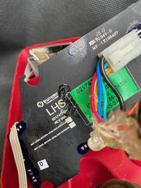
The main PCB has three DC-DC convertors to run the three main light circuits (probably constant current high frequency switching circuits). The power is supplied via a standard wiring connector on the rear of the unit. The board is conformally coated to protect the electronic components from environmental damage.
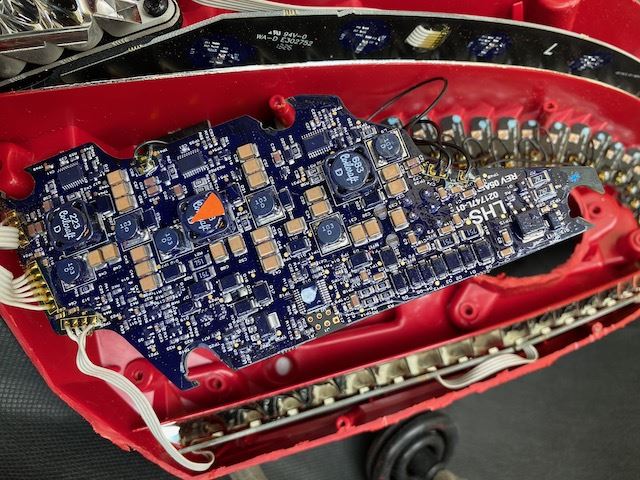
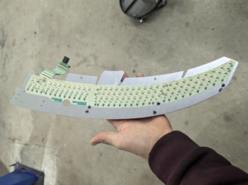
Each of the 25 small LED boards is fixed with an individual torx head screw.
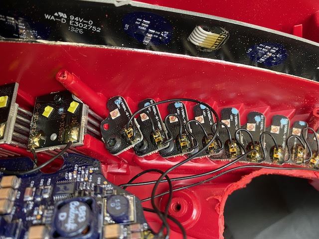
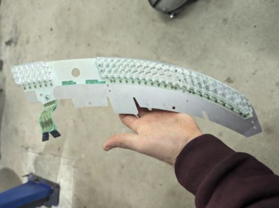
The whole led assembly!
Micro-controller
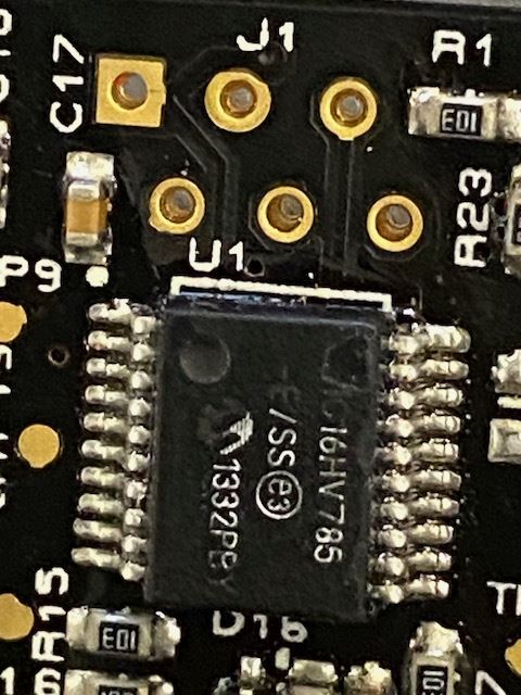
A micro-controller is present on the board to control the logic of the LEDs. The controller on this board is a microchip 16HV785/SS 8-bit microprocessor with 2K of flash. This device is more than adequate to deliver the high intensity for the sidelight brakes and the indicator flashing. The firmware for this device is loaded using the 6 gold plated test pin connector on the PCB. This firmware is easily readable, unless the manufacturer has set the code protection flag. The 16HV785 device is also capable of updating its own firmware, so it's possible that the firmware has corrupted. I have lots of experience with these device and such a failure mode is not uncommon.
Datasheet
The reversing light is a separate unit with its own own heatsinks. This board is permanently bonded to to heatsink and this is in turn bonded to the moulding. The PCB is difficult to remove as it's bonded to the heatsink with double-sided heat conducting tape.

The rear moulding is very complicated, and the reflective silvering is applied directly to the moulding. The moulding will not be completely sealed, so air will be forced in and out by changes in atmospheric pressure. Should water condensation form, it will be necessary to vent the unit to dry it out. This may need holes to be made in the unit.
The lights look great when on. They have been designed that way. However, in my opinion they are a very poor design with no regard to production engineering and no prospect of long term maintenance or repair. The fact that they are incredibly difficult to manufacture is not really an issue. They are made in small numbers, with no cost issues, so the time required for assembly is not important. If this design is model-specific it is hard to justify the tooling and design costs. The design and engineering effort and cost could probably have been better used elsewhere.
This specific PCB has been designed by Trumeter, a large design consultancy. They do not list vehicles as one of their specialities. Why someone with no vehicle design was used is not what I would expect.
The boards use a standard break out technique where the whole lot of PCB’s would have been manufactured and tested as one piece. Just before being placed into the light moulding the boards are then broken out to the individual parts.
Reason for failure?
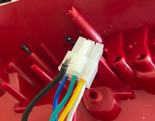
The wiring going to a 6 wire connector on the back of the main PCB. The PCB worked OK once removed so the connector wiring was examined. The black (0 volts) wire was loose. This is a manufacturing fault. This wire should be stressed-relieved by the crimp. The black wire is thicker than the others so it is possible it was crimped using the wrong sized crimping tool. Operating the circuit with no good 0 Volt return could damage components.
On more examination, the logic controller was found to be getting 5 volts but does not seem to be operational. The coating on the PCB made probing the circuit difficult.
The future
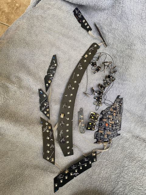
The unit has 9 large circuit boards and 20 small circuit boards, 8 multiway cables and 25 single wires all soldered at each end. The wiring joints are all mechanically fixed in position with resin.
There are about 100 LED’s and the same number of semiconductors, along with a couple of hundred passive components. This is in a lamp unit that is subject to lots of movement, temperature changes, etc.
This configuration with so much wiring is a reliability nightmare. We know of several failures, and rear lights are also very liable to crash damage. If AML cannot keep the units in supply there will be no repairability without massive retooling costs.
The £3,500 replacement cost gives a cost to AML of about £350 (given the industry's normal x10 mark-up on car spares. This parts cost is reasonable given the complexity, although I would argue that the board was far too complicated for the very simple task it needs to accomplish.
This era of car will probably not become usable classics unless some considerable effort is put into securing the tooling for the plastic parts and/or to produce a reliable and simple led driver board. Given the very simple logic of these LED’s this should be relatively easy.
Using prebuilt simple LED drivers such as this may be viable - https://www.sparkfun.com/products/13705
Update 2/3/2023 :
This is the board from a DB9. It looks so sensible and has LED's on both sides. It is a flexible PCB stuck to a bent piece of aluminium. It has 2 LED's and a single resistor in series. These are all paralleled up. This is proper engineering and highly reliable.
Gary Ungless
